
If you own a 2003-2007 Ford Super Duty, you already know the 6.0 Powerstroke’s reputation. It earned it. But here’s the part most conversations miss: the engine block itself is solid. The rotating assembly can handle 500 horsepower on stock internals. What kills these trucks is the stuff bolted to the engine — and nothing fails more predictably than the EGR cooler.
Changing the EGR cooler itself is a straightforward mechanical job. The catch — and the reason so many owners do this job twice — is that a failed EGR cooler is usually the victim, not the criminal. The real problem lives one component upstream: the engine oil cooler. If you replace the EGR cooler without checking the oil cooler, you’re buying yourself 20,000 miles at best before the new cooler fails the same way.
How a 6.0 EGR Cooler Fails — The Chain Reaction
To understand why the EGR cooler fails, you need to understand what happens before it fails. The sequence is consistent across nearly every 6.0 that comes into a shop with a blown cooler:
Step 1 — The Oil Cooler Clogs
The 6.0 block was cast using a sand-mold process that leaves microscopic silica particles embedded in the iron water jackets. Over time, vibration and thermal cycling break those particles loose. They circulate through the cooling system and eventually reach the oil cooler. The oil cooler’s internal passages are narrow. Silica plugs them. Coolant flow through the oil cooler drops to a trickle, then stops entirely.
Step 2 — The EGR Cooler Starves
The coolant that exits the oil cooler flows directly into the EGR cooler. When the oil cooler is clogged, the EGR cooler runs dry. Exhaust gas temperatures in the cooler can exceed 1,200°F. Without coolant flowing through it, the thin-walled internal tubes heat-cycle until they fatigue and crack.
Step 3 — Coolant Enters The Intake.
Once the internal tubes rupture, engine coolant leaks into the exhaust gas stream, which feeds directly into the intake manifold. The engine burns coolant. White smoke pours from the tailpipe. If enough coolant pools in a cylinder, the engine hydro-locks on startup — and that’s a bent connecting rod and an engine teardown.
The takeaway: replacing the EGR cooler without checking the oil cooler is like replacing a blown fuse without finding the short. You will do it again.
Symptoms: How to Know Your EGR Cooler Has Failed
The classic signs:
-
White smoke from the exhaust, especially at idle after the engine warms up. Diesel exhaust should be clear or have a light gray haze under load. Thick white smoke that smells sweet is coolant burning in the combustion chamber.
-
Unexplained coolant loss. The degas bottle keeps dropping, but there’s no visible leak on the ground. The coolant is exiting through the exhaust.
-
A sweet, syrupy smell at the tailpipe. If you walk behind the truck while it’s idling and smell something closer to a cotton candy machine than diesel exhaust, coolant is getting into the cylinders.
-
Low coolant warning on the dash with no visible external leak.
-
Hydro-lock on startup. The engine cranks once, stops dead, and won’t turn over. This is the worst-case scenario — coolant has filled a cylinder and the piston can’t compress liquid. Stop cranking immediately and have the engine inspected before you bend a rod.
These symptoms overlap with a blown head gasket, which is another common 6.0 failure. The bubble test below tells you which one you’re dealing with.
Diagnosing the EGR Cooler: The Degas Bottle Bubble Test
Before you order parts, confirm the EGR cooler is the source. This test takes 10 minutes and tells you whether exhaust gas is entering the cooling system — and whether it’s coming from the EGR cooler or the head gaskets.
What you need: A section of clear plastic tubing (⅜" works well), a water bottle half-filled with water, and tape to seal the connection.
Procedure:
-
Let the engine cool completely. Remove the degas bottle cap only when the system is cold and no pressure remains.
-
Attach one end of the clear tubing to the degas bottle’s overflow port. Seal it tight — electrical tape or a zip tie works. The connection must be airtight.
-
Submerge the other end of the tubing in the water bottle. You want the tube opening about an inch below the water surface.
-
Start the engine and watch the water bottle. A steady stream of bubbles means combustion or exhaust pressure is entering the cooling system.
-
Now the diagnostic step: unplug the VGT (variable geometry turbo) actuator solenoid on the turbo. This disables the turbo’s variable vane function and, critically, reduces exhaust backpressure.
Reading the result:
-
If the bubbles stop or slow significantly when you unplug the VGT, the leak is in the EGR cooler. Reduced backpressure means less exhaust gas is being forced through the cracked cooler into the coolant.
-
If the bubbles continue unchanged, the leak is likely a head gasket. Combustion pressure is bypassing the head gasket into the coolant jacket, and changing turbo backpressure won’t affect it.
To visually confirm an EGR cooler failure: Remove the EGR valve (two bolts on top of the intake manifold) and look inside the intake with a flashlight. If you see moisture, wet carbon, or a “steam-cleaned” patch on the intake wall where the EGR gases enter, the cooler has been leaking coolant into the intake.
The Oil Cooler Test — Do Not Skip This
This is the step that separates a 100,000-mile repair from a 20,000-mile repair. If the EGR cooler failed because the oil cooler is clogged, and you don’t replace the oil cooler, the new EGR cooler will fail the same way within months.
Procedure:
- Drive the truck until it reaches full operating temperature — at least 20 minutes of highway driving. You need the oil and coolant fully heat-soaked.
- On a flat road at a steady 65 mph with no load, read both temperatures.
- Calculate the delta: EOT minus ECT.
The 15-degree rule: A healthy 6.0 typically runs a 5°F to 10°F delta. At 15°F, the cooler is clogged enough to restrict coolant flow to the EGR circuit. At 20°F or higher, you’re on borrowed time.
If your delta is under 15°F and the EGR cooler failed anyway — it does happen, especially on high-mileage trucks where the cooler simply fatigued from heat cycles — you can replace just the EGR cooler. But if the delta is 15°F or above, plan to do both.
TruckTok EGR Delete Kits: When Replacement Won’t Cut It
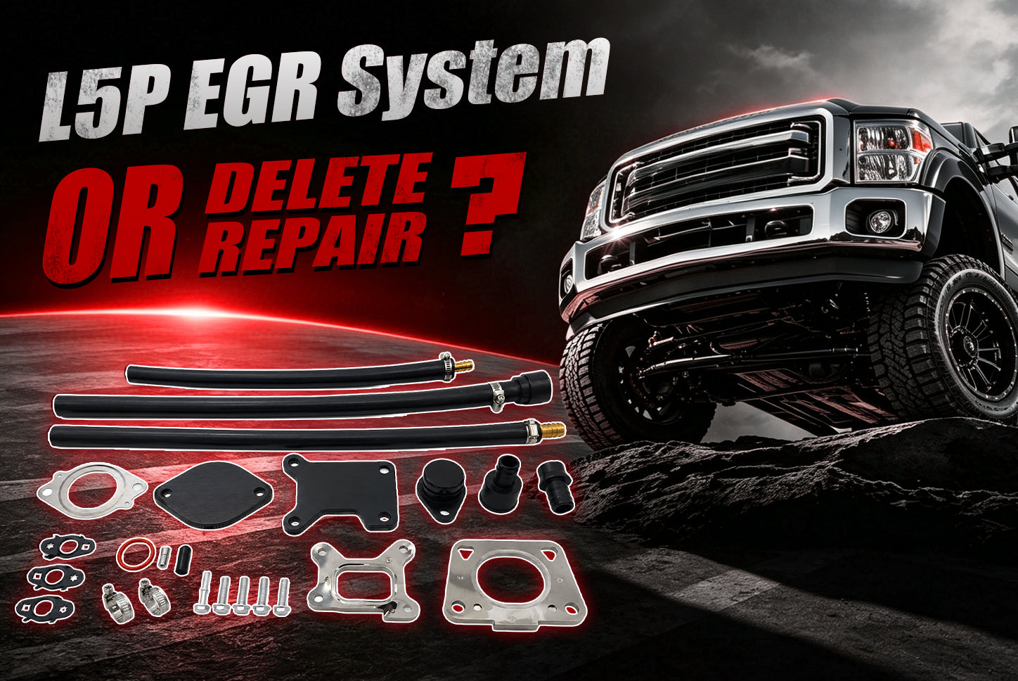
If you’ve decided the delete path is right for your truck, TruckTok stocks two kits that cover the full range of needs — from a budget-friendly baseline to an everything-you-need solution with upgraded piping.
2003-2007 6.0L FORD Powerstroke Diesel EGR Delete Kit Fits (SKU ER-0067)

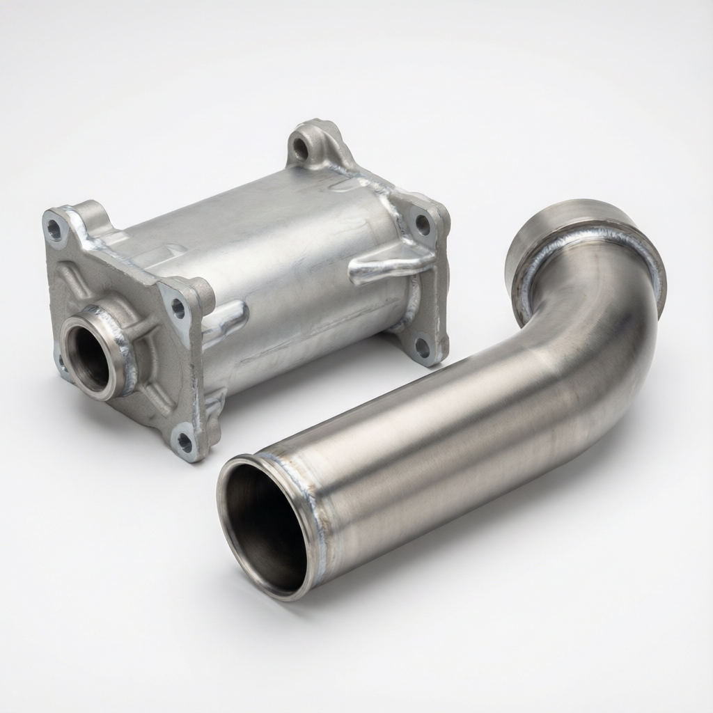
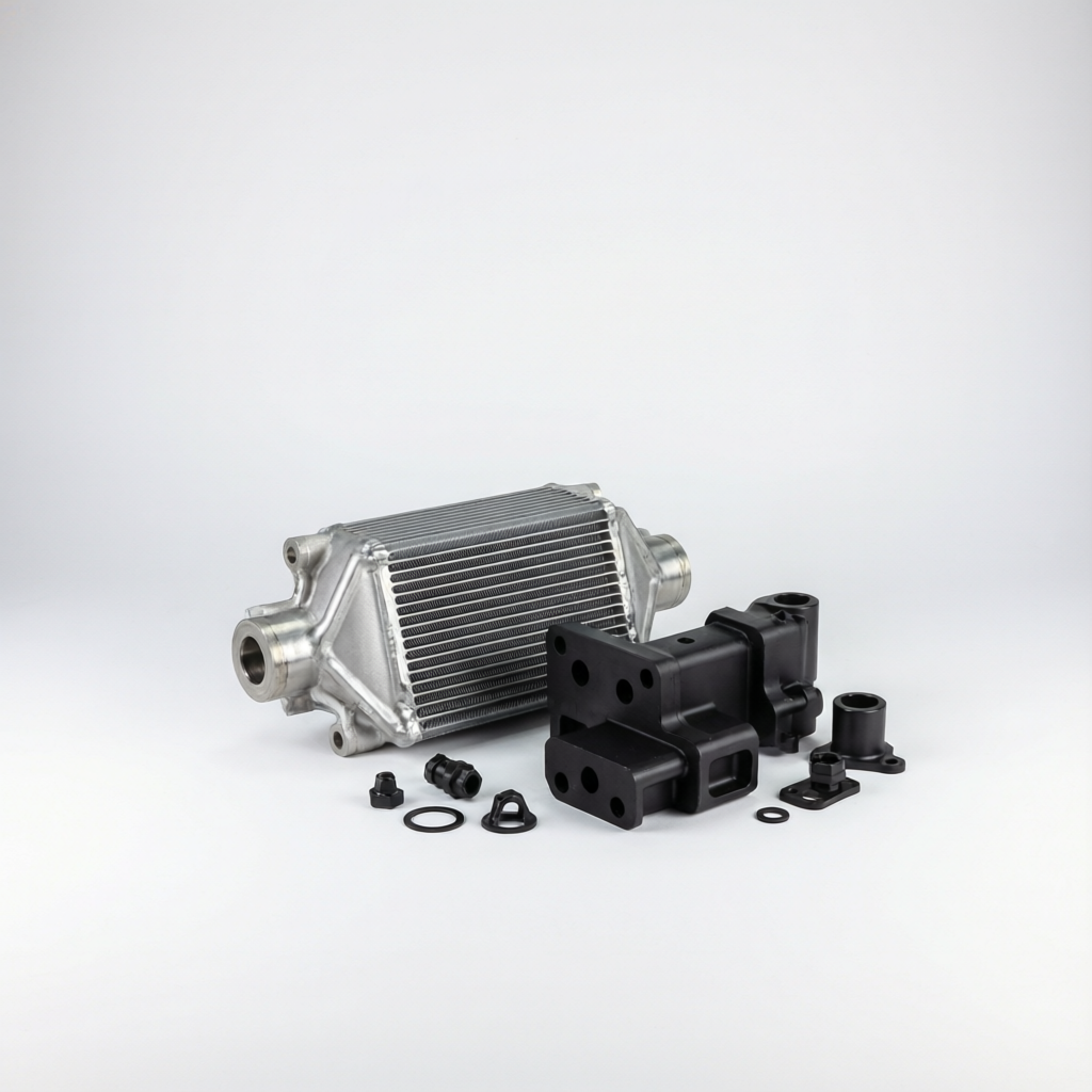
- The entry-level EGR delete kit, precision CNC-machined billet aluminum block-off plate and 304 stainless steel J-tube permanently eliminate the factory EGR cooler.
- The billet aluminum coolant reroute tube connects between the oil cooler cover and the water pump, redirecting coolant exactly where it needs to go while bypassing the fragile factory setup.
- Fits 2003-2007 F-250/F-350/F-450/F-550 and 2003-2007 Excursion with the 6.0L.
2003-2007 6.0L Ford F250 F350 Powerstroke Diesel EGR Basic Cooler Kit (SKU ER-0134)

- This EGR delete kit upgrades the thin, failure-prone factory connection lines to 304 stainless steel tubes that handle thermal expansion without cracking.
- Precision-cut, heavy-duty steel block-off plates seal off the exhaust port permanently, while marine-grade silicone couplers with high-temperature reinforcement ensure zero boost or coolant leaks at every sealed port.
- Fits 2003-2007 6.0L Super Duty and 2004-2010 E-Series vans.
Both kits require a tuner to disable the EGR-related DTCs and prevent a check engine light — the ECM will detect the blocked exhaust flow. Plan on pairing either kit with a tuner like the H&S Mini Maxx or an SCT X4.
Tools, Parts, and Supplies
This is an advanced DIY job. Turbo removal and intake manifold disassembly put it firmly in the “experienced home mechanic” category. Expect 6 to 8 hours for a first-time install — longer if you hit seized bolts.
Tools:
- Metric socket set (8mm, 10mm, 13mm, 15mm, 18mm) with ⅜-inch ratchet, long extensions, and swivel joints
- 24-inch pry bar — an 18-24 inch bar is a must-have for separating components, aligning exhaust connections during reassembly, and popping the turbo loose from the pedestal
- T30, T40, and T45 Torx bits. The oil cooler uses T30 and T45; the intake manifold uses T45
- Torque wrench covering inch-pounds (for intake bolts at 96 in-lb) and foot-pounds (for turbo hardware at 23-28 ft-lb)
- Combination wrenches, 8mm through 22mm. A 7/8" (same as 22mm) is handy as a backup wrench when removing fan shroud bolts
- Ratcheting wrenches — a 10mm ratcheting wrench saves time and knuckle skin on the turbo supply line and FICM bolts
- Pick set for O-ring removal and cleaning Torx bolt cavities before inserting bits
- Hose clamp pliers or channel locks
- Penetrating oil (PB Blaster or WD-40 — apply to V-band clamps and exhaust fasteners the day before if possible)
- Large coolant drain pan (4+ gallons capacity)
- Clean shop rags, caps, and plugs for open ports
- ScotchBrite pad — for cleaning sealing surfaces on coolant fittings and oil cooler mating surfaces without damaging aluminum
- Assembly lube, engine oil, or silicone grease — for holding O-rings and seals in place during reassembly
Supplies:
- 3-4 gallons of Motorcraft Gold coolant or an ELC rated for diesel engines. Do not mix coolant types — flush the system completely if switching.
- Carb cleaner or brake cleaner — plan for at least two cans. The intake manifold will be packed with soot.
- Engine oil and filter (change during the job)
- Fuel filter (the housings come off anyway)
- Blue Loctite for reassembly
- Replacement O-rings: turbo oil drain O-ring, turbo pedestal O-rings, EGR valve O-rings (Ford part VC-8), intake manifold gaskets. Ford charges $5-7 for individual O-rings — buying multi-packs from aftermarket suppliers saves money.
- Simple Green and Dawn dish soap — for pre-flushing the cooling system before the repair (see Step 1)
- ½-inch PVC male adapter with a garden hose thread fitting — a $3 DIY flush adapter for the heater hose circuit
Step-by-Step: Changing the EGR Cooler on a 6.0 Powerstroke
Step 1: preparatory work
Park on a level surface and let the engine cool completely — at least two hours after shutdown. Hot coolant under pressure causes severe burns.
Disconnect Batteries
Disconnect both negative battery terminals. The 6.0 uses two batteries, and disconnecting only one leaves the electrical system partially live. You’ll be working around the alternator and starter wiring throughout the job — having the batteries disconnected prevents accidental arcs.
Drain Coolant
Remove the degas bottle cap only after the system is cold. Place a clean drain pan under the radiator petcock on the driver’s side bottom of the radiator, open it, and drain. Remove the engine block drain plugs (8mm Allen) on each side of the block to get more coolant out. Expect 3-4 gallons.

Pre-flush The Cooling System.
Before installing a new EGR cooler, flush the entire system to remove the silica, casting sand, and oil-contaminated sludge that caused the failure in the first place. Here’s the driveway method:
- With the lower radiator hose off and the degas cap off, disconnect the heater hose from its hard pipe on the intake. Slide a ½-inch PVC male adapter with garden hose threads into the heater hose end (a bit of oil helps it slide on).
- Connect a garden hose and run water through the system. You’ll see dark, sludgy water coming out the bottom radiator hose.
- Drain, then refill with water and a cup each of Simple Green and Dawn dish soap. Run the engine up to temperature. Drain. Repeat until the discharge runs clear — usually four to five cycles.
- After the final flush, drain fully and remove the block plugs to evacuate as much remaining water as possible.

Take photos of hose routing, wire clips, and clamp positions before anything comes apart. Reference them during reassembly. Bag and tag every set of bolts — the 6.0 intake uses multiple lengths in specific positions, and mixing them causes stripped threads or incomplete sealing.
Step 2: Clear the Top of the Engine
The EGR cooler lives under the intake manifold at the back of the engine valley. Everything above it has to come off. Work carefully — the wiring loom and plastic connectors on these 15-20 year old trucks are brittle. If you hear cracking while manipulating a wire loom clip, cut it with wire snips instead of forcing it and breaking the connector underneath.
Remove in this order:
-
The coolant degas bottle. Be careful with the plastic overflow nipple — it snaps easily. If it breaks, a brass barb fitting epoxied into the bottle is the standard repair.
-
Air filter housing and intake tube. Disconnect the mass airflow sensor if equipped.
-
Turbo inlet tube (metal or plastic depending on model year). Leave the filter minder line attached and move it aside as a unit.
-
CCV (crankcase ventilation) tube.
-
The passenger-side charge-air cooler pipe (boost tube). On the 05+ plastic tubes, if they don’t slide off easily in cold weather, hit them with a blow dryer to soften the plastic — forcing them cold cracks the ends.
-
The driver-side charge-air pipe.
-
The alternator. Remove the belt by pulling the tensioner and latching it in the service position, then unbolt the alternator (13mm for the mounting bolts, 10mm for the rear nut on the main power wire).
-
The FICM (fuel injection control module). Disconnect the three lower connectors — push each connector up harder into the FICM first, then squeeze both sides and rock it downward.
-
The upper fuel filter bowl and oil filter housing. Remove the four fuel lines (hold the fitting with a backup wrench while loosening the nut), the banjo bolt at the rear, and the four T45 Torx bolts.
Critical connector health check: The blue or white plastic retaining clips on the ICP and EBP sensor connectors prevent the connector from wiggling loose over time. Without these clips, the connector vibrates and causes surging at idle — a common complaint.
Step 3: Remove the Turbocharger
The turbo sits directly above the EGR cooler. On most 6.0 Powerstrokes, there’s no workaround — it has to come out. One rule from experienced hands that will save you hours of frustration: do not loosen the up-pipe bolts. Leave the up-pipes fully tightened at both ends.

-
Apply penetrating oil to the V-band clamps on the up-pipe, downpipe, and intake Y-pipe. Let it soak for at least 15 minutes — overnight if the clamps are original. You’ll know the clamp is free when it makes an audible “pop” sound.
-
Disconnect the downpipe V-band clamp. For stock exhaust, there’s a retaining clip that holds the downpipe in position; aftermarket exhausts lack this clip and will need manual support during reassembly.
-
Disconnect the up-pipe V-band clamp. If it’s stuck, don’t force it — spray more penetrant, tap it with a punch to break the rust bond, then try again.
-
Unplug the VGT actuator connector on the passenger side. Early models use a metal band you unhook; 05+ use push-in clips. Minimal prying — these break easily.
-
Disconnect the turbo oil feed line (8mm for the fitting at the turbo, two 10mm nuts at the oil cooler housing). The oil supply line is a rigid pipe on later models — the replacement part with the flex hose section is an upgrade that improves oil flow to the turbo.
-
Remove the turbo oil drain tube. It’s a rigid pipe that seats into an O-ring in the turbo pedestal. Spray the base with penetrant and wiggle it straight up and out.
-
Remove the three turbo mounting bolts (all 10mm). Two are visible at the front; the third is hidden at the back near the firewall. A 10mm swivel socket on an 18-24" extension is the only way to reach it. Slide the extension through from the passenger side.
-
Lift the turbo. Use a pry bar between the turbo base and the pedestal to break the seal, then rotate the turbo roughly 45 degrees toward the driver’s side as you lift — this angles the drain tube and the compressor outlet away from obstructions. Watch the oil drain tube as it clears the pedestal.
A note on the oil filter housing: The aftermarket tall oil filter caps (seen on many trucks) can obstruct the turbo during removal. If you have one, either remove it first or be careful not to snap the oil standpipe underneath while maneuvering the turbo out.
Step 4: Remove the Turbo Pedestal and EGR Cooler Connections
With the turbo out, remove the four pedestal bolts and lift the pedestal off the engine block. Before reinstalling it later, replace the large O-ring at the base where it mates with the oil cooler housing — this O-ring is included in the oil cooler kit.
Disconnect the coolant hoses going to and from the EGR cooler. The main coupler hose from the oil cooler housing has a spring-steel retaining clip inside. Align the notch on the stainless steel coupler to the 12 o’clock position, then slide the hose back. If it’s stuck, pry it back with a screwdriver — as long as the nipple doesn’t break, no damage is done. Expect residual coolant — keep the drain pan underneath.
Remove the clamp connecting the EGR cooler to the passenger-side up-pipe. This is the exhaust inlet for the EGR circuit. As with the turbo clamps, penetrating oil and patience are your tools here. You can feed the clamp forward around the bolt that holds a small cover — spread it open, walk it past, and leave it resting on the front of the intake while you work.
Step 5: Remove the Intake Manifold and EGR Cooler
The intake manifold on a 6.0 is a horseshoe-shaped casting that wraps around the back of the engine valley. The EGR cooler sits inside it.

-
Disconnect the EGR valve electrical connector. Remove the two bolts holding the EGR valve and pull it straight up. If it’s stuck from carbon buildup, wiggle it gently — don’t pry against the sealing surface.
-
Take a photo or clearly mark the intake manifold bolt positions. There are approximately 18 bolts in multiple lengths, and some (particularly the rear ones) have studs for wiring harness brackets. Mixing them during reassembly will strip threads or leave the intake loose.
-
Remove all intake bolts. A 24-inch pry bar slipped into the side of the intake provides enough clearance to reach the back bolt.
-
Bend the heater hose bracket tab upward slightly — just enough to clear the intake during removal. It bends back easily.
-
There’s a fuel line bracket on the front of the intake held by a notably shorter bolt than the rest. Bag it separately and label it “front bracket bolt.”
-
Before lifting the intake, blow the area around all open ports with compressed air. Look for dropped washers, nuts, injector clips — anything that could fall into a cylinder. Drag a magnet through the valley.
-
Lift the intake manifold up at the front and pull it forward and out. Watch the fuel lines on the passenger side and the A/C line as you clear the engine. The EGR cooler comes up with the intake as a unit.
-
On the workbench, unbolt the failed EGR cooler and remove the old gaskets and O-rings.
A reassembly trick that eliminates grief: When reinstalling the intake, the metal gaskets can be nearly impossible to line up — the factory bolts are too short to reach through the intake and gasket simultaneously. Use two longer bolts (temporarily borrowed from the turbo pedestal mount) to hold the gasket in place and get the intake aligned.
Step 6: Clean Everything — Completely and Obsessively
This is the most tedious part of the job, and it’s the one that determines whether the repair lasts or comes back with a vengeance. Two areas demand total attention: the intake manifold and the IPR screen.
Intake Manifold:
Years of EGR operation have coated the inside with a thick layer of carbon soot. Installing a new cooler into a soot-packed manifold restricts airflow from day one. Spray the inside with carb or brake cleaner. Let it soak. Scrub with a stiff-bristle brush.
Intake Gaskets:
Inspect each gasket. The raised rubber lip faces into the intake manifold, not into the cylinder head — if you install them backwards, you’ll get a boost leak. If the rubber is hard, cracked, or torn, replace them.
Step 7: Build the Oil Cooler Assembly
If you’re replacing the oil cooler alongside the EGR cooler, build the assembly on the bench before installing it in the truck.
-
Separate the housing. Remove the four 13mm bolts holding the cooler cover to the housing. These are specific-length bolts — using a longer substitute will punch through the casting and create an oil leak.
-
Replace all seals. Lubricate the O-ring grooves with assembly lube or silicone grease — this holds the seals in place during assembly so they don’t shift or fall out. The two large O-rings that seal the cooler brick are different sizes. The larger one goes in the housing side; the smaller one goes in the cover.
-
Press the new cooler brick in. Lubricate the sealing surfaces generously. Line up the hex shape on the cover-side O-ring and press the cover straight down onto the brick. Do not rock it — that’s how O-rings get pinched. Torque the four bolts evenly.
-
Install the blue perimeter gasket. It only fits correctly one way. Press it straight down into the groove with your thumbs — don’t work it in from side to side, which stretches the gasket and causes leaks. Once it’s fully seated, run your finger around the entire perimeter to verify no section has popped out.
-
Before setting the assembly in the valley: Blow out all the bolt holes in the engine block with compressed air. These are blind holes, and they fill with oil and coolant during disassembly. If you don’t clear them, the fluid hydraulic-locks the bolt and you get a false torque reading — the bolt feels tight but the housing isn’t actually clamped down.
Step 8: Install the New EGR Cooler
Bolt the new EGR cooler to the intake manifold with fresh gaskets. Lubricate the O-ring on the exhaust inlet end before fitting.

One critical trick from experience:
When you first install the EGR cooler, only finger-tighten the bolts — leave about a half-turn of play in them. This gives you the wiggle room you need later when you’re lowering the intake manifold onto the engine and trying to align the EGR cooler’s exhaust inlet flange with the up-pipe. Once the intake is fully seated, bolted down, and the up-pipe connection is aligned, go back and final-tighten the EGR cooler bolts and the rear band clamp.
Step 9: Reassemble in Reverse Order
The reassembly sequence matters. Here are the critical techniques that separate a clean, leak-free result from a comeback job:
Intake manifold. With the intake gaskets properly oriented (rubber lip up into the manifold) and held in place by a few bolts, lower the intake onto the engine. Once the intake is fully seated, start all bolts by hand before torquing any of them. Torque to 96 in-lb (inch-pounds) evenly, working in three passes — snug, then tighten, then final torque.
Tighten the EGR cooler. Now that the intake is torqued and everything is aligned, tighten the EGR cooler bolts to spec. Reach back with the rear band clamp and squeeze it closed around the up-pipe flange — position the clamp roughly vertical for easiest access.
Turbo pedestal. Install the pedestal with a new O-ring at the base. There’s no gasket sealer needed — the O-ring does the sealing.
Turbocharger. The trickiest part of the whole job is lowering the turbo while simultaneously aligning the oil drain tube, the downpipe, and the up-pipe connection. Approach it like this:
- Position the turbo roughly sideways over the pedestal, then rotate it as you lower it.
- Line up the oil drain tube first — it must drop straight into the pedestal bore. Use your hand behind the turbo to push the downpipe out of the way while you get the drain tube started.
- Once the drain tube is entering the pedestal and the turbo feels seated, align the up-pipe to the turbo exhaust inlet. For 05+ trucks with the exhaust bracket, a pry bar between the up-pipe and the bracket pushes the two flanges together easily.
- Fit the V-band clamp before tightening any turbo bolts. Once everything is aligned, install the three 10mm turbo mounting bolts and torque to 23-28 ft-lb.
V-band clamps. The factory torque spec for these clamps is often listed, but in practice, experienced techs use the spring-compression method: tighten the clamp nut until the spring compresses and you feel a noticeable increase in resistance, then stop.
Fuel and oil housings. Reinstall the oil filter housing and fuel filter bowl. When seating the fuel filter housing, tighten the T45 bolts evenly — these housings have small cast ears that will snap off if one bolt is fully tightened while the others are loose.
Charge-air pipes. Clean all mating surfaces thoroughly — oil residue on the pipe ends will cause the boots to slip off under boost. For the 05+ style plastic cold-side tube, position the V-band clamp so the bolt is out of the way of the air filter snorkel. When installing the passenger-side hot-side tube, start it on the charge-air cooler first, then work the upper connection onto the intake Y-pipe.
The wiring harness. Routing the wire loom correctly prevents chafing and electrical issues. The glow plug wiring goes under the main wire loom. Each injector connector should click into place — if one doesn’t seat, find out why instead of forcing it.
Fan shroud. Feed the shroud down between the engine and radiator. From underneath, use a pry bar to pull the radiator forward slightly while pushing the shroud down until the tabs lock into the radiator slots. If you’re doing this solo, get one corner started, then work your way around.
Step 10: Refill, Bleed, Prime, and Start
Coolant Fill
Refill slowly with the correct coolant — about 2 gallons initially, then pause and squeeze the upper radiator hose to burp air pockets. Continue filling. The 6.0 cooling system traps air in the oil cooler housing, EGR cooler, and heater core. Leave the degas cap off during the initial startup so you can top off as the thermostat opens.
Prime The Oil System Before Starting
This step is non-negotiable after any repair where the oil cooler was opened or the turbo was removed. The HPOP and turbo bearings are dry and will be damaged by even a few seconds of unprimed running.
First Startup
Reconnect the starter wire and both battery cables. Key on and check for CEL or warning lights. Start the engine and:
- Watch the oil pressure gauge — if it doesn’t register within 5 seconds, shut it off.
- Scan the engine valley with a flashlight for the first 2-3 minutes. The turbo oil drain O-ring is the most common leak. If oil or coolant appears, shut it down and address it now — the valley will fill faster than you think.
- Listen for an exhaust tick or boost hiss — either indicates an improperly seated V-band clamp.
- As the engine warms, the degas bottle level will drop when the thermostat opens. Top it off slowly. You’ll see residual brake cleaner and assembly lube burn off — the engine may stumble or smoke briefly. This is normal.
Post-startup Cooldown
Let the engine reach full operating temperature, then shut it down and let it cool completely. Recheck the degas level. Recheck the valley for leaks. Recheck nothing else — the gaskets and O-rings are designed to seal at their specified torque and should not be re-torqued.
Change the engine oil and filter. Any coolant that entered the intake before the repair may have contaminated the oil. Also, debris from the cleaning process inevitably finds its way into the oil. Fresh oil and a new Motorcraft filter are cheap insurance.
Final Drivability Check
Take a short test drive. Run the oil cooler delta at a steady 65 mph on flat ground with a scan tool — it should now read under 10°F if you replaced the oil cooler. Do not tow or load the engine hard for the first 50 miles.
Post-Install Checklist
- Coolant level is stable after a full heat cycle and cool-down
- No oil or coolant in the engine valley
- No exhaust tick or boost hiss at idle or under light throttle
- No white smoke from the tailpipe (residual moisture steams off initially — this is normal)
- No new CEL or stored codes
- Oil cooler delta under 10°F at highway cruise
- No rough idle or surging (indicates a missing ICP/EBP connector clip)
Conclusion
The 6.0 Powerstroke EGR cooler failure is predictable, diagnosable, and fixable in a driveway with hand tools and a full day — if you treat the oil cooler as part of the same job.
Run the delta. If it’s over 15°F, do both coolers in one shot. Upgrade to a Bulletproof or AFE unit and add a coolant filter while you’re in there. If the truck lives off-road and the delete route makes more sense, TruckTok has two kits that cover both ends of the spectrum: the EGR Delete Kit for a budget baseline, and the EGR Basic Cooler Kit with upgraded stainless piping and marine-grade couplers for the owner who wants it done once. Both ship free and are in stock now.
Every step that feels like extra work — the pre-flush, the IPR screen cleaning, the dry cranking — is the step that prevents you from being the guy who did this job twice.
Frequently Asked Questions
Q1: Can I replace the EGR cooler without removing the turbo?
Not practically. The turbo blocks access to the intake manifold bolts, the EGR cooler clamps, and the coolant connections. Removing it adds time but gives you the access you need.
Q2: Why did my new EGR cooler fail after only 20,000 miles?
Almost certainly a clogged oil cooler. The oil cooler feeds coolant to the EGR cooler, and when it’s restricted, the EGR cooler runs hot and fails the same way the original did. Always run the delta test first.
Q3: How long does this job take?
Experienced tech: 4-6 hours. First-time DIY: a full 8-hour day or a weekend. Stuck V-band clamps, seized fasteners, and cleaning the intake manifold account for most of the extra time.
Q4: Is the Bulletproof EGR cooler worth the extra cost over OEM?
Yes, if you plan to keep the truck. The braided-tube design eliminates the honeycomb failure point and carries a lifetime warranty. OEM costs $300-$450 and fails the same way in 60,000-80,000 miles if cooling system maintenance isn’t perfect.
Q5: What happens if I ignore a leaking EGR cooler?
The leak worsens. Coolant pools in a cylinder while the engine is off. On the next startup, that cylinder hydro-locks — the piston compresses a liquid that doesn’t compress. The connecting rod bends. You’re now doing an engine rebuild instead of an EGR cooler replacement.
Q6: Do I need a coolant filtration system?
Not mandatory, but strongly recommended if the old oil cooler was clogged with silica and casting sand. A BD Diesel filter splices into the heater hose circuit and traps debris before it reaches the new oil cooler. Change the first filter after 200 miles, then every six months.
Q7: Can I reuse my intake manifold gaskets?
Yes — Ford’s service procedure allows it. Inspect each gasket: the rubber lip must be pliable and sit above the plastic carrier. If the rubber is hard, cracked, or torn, replace them. Install them with the rubber lip facing up into the intake, not down into the head.
Q8: The truck started but now I have a rough idle and the RPMs are jumping around — what did I do wrong?
Check the plastic retaining clips on the ICP and EBP sensor connectors. Without those clips, the connector vibrates loose and the PCM gets erratic sensor readings, causing surging. If the clips are missing, either replace the pigtail or use zip ties to hold the connector firmly seated.